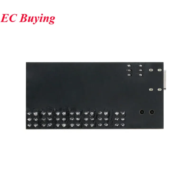
Voltage Regulator Module – Multi-Output Board
1 piece
$17.99
Sale price
$17.99
Regular price
$0.00
Skip to product information


Voltage Regulator Module – Multi-Output Board
$17.99
Sale price
$17.99
Regular price
$0.00
Organize Your Prototype Around One Voltage Board
Spend less bench space on scattered voltage connections. This voltage regulator module groups labeled outputs and color-coded headers on one compact board, helping you keep a prototype easier to follow. Solder-pad, USB-C and DC-socket input formats give you several connection arrangements, with one- or two-board packs for your next build.
Key Benefits
- Labeled output positions — Identify the available voltage connections directly on the board.
- Multiple input formats — Use the listed solder-pad, USB-C or DC-socket input arrangement.
- One- or two-board packs — Choose a single module or keep a second ready for another build.
Instead of spreading unrelated regulator modules across a prototype, start with a board that brings the connection points together. The supplied instructions require the input voltage to be at least 1.5V above the intended regulated output; match the source and load to the board's requirements.
Frequently Asked Questions
Which regulated outputs are listed?
The supplied listing identifies 1.2V, 1.5V, 1.8V, 2.5V, 3.3V and 5V connections.
What input connectors are listed?
The description identifies solder pads, USB-C and a DC socket.
What does G identify?
The supplied wiring notes identify G as the input/output negative connection.
How many modules can I order?
One-piece and two-piece options are listed.
Can the input equal the regulated output voltage?
The supplied instructions require the input to be at least 1.5V higher than the intended output.
SPECIFICATIONS
Application: Computer
Brand Name: MFG
Choice: yes
Condition: New
High-concerned chemical: none
Origin: Mainland China
Package: Module
Regulated Output Voltages: 1.2V/1.5V/1.8V/2.5V/3.3V/5.0V
Type: Voltage Regulator
is_customized: Yes
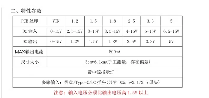
Multiple input: Pad/Type C/DC socket (compatible with DC5) 5 * 2 1/2 5 female heads)
Attention: The input voltage must be at least 1.5V higher than the output voltage
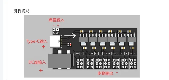
VIN input positive pole
Type-C/DC socket input
VIN/1.2/1.5/1.8/2.5/3.3/5 output positive pole
G input/output negative pole
Note: The output VIN can also be used as input